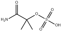
2-methyl-2-(sulphooxy)propionamide synthesis
- Product Name:2-methyl-2-(sulphooxy)propionamide
- CAS Number:49562-37-0
- Molecular formula:C4H9NO5S
- Molecular Weight:183.18

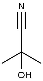
75-86-5
2 suppliers
$64.90/5G

49562-37-0
1 suppliers
inquiry

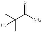
13027-88-8
113 suppliers
$21.00/1g

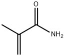
79-39-0
293 suppliers
$13.00/25g
Yield:-
Reaction Conditions:
with sulfuric acid at 85 - 101; for 0.666667 h;Product distribution / selectivity;CSTR reactor;
Steps:
1
A first hydrolysis process (“Prior Art”) of the type disclosed in Kirk-Othmer and US '093 is illustrated by FIG. 2, and comprised two CSTR reactors in series. This system was operated at an H2SO4:ACH molar ratio of 1.48, and at a 2.3:1 ACH addition split, wherein 70% by weight of the total ACH feed was added to the first reaction stage, and 30% by weight of the total ACH feed was added to the second reaction stage. Sulfuric acid at a concentration of 99.5% and ACH at a concentration of 98.5% were utilized as reactants in this system. Specifically, the 1st reaction stage of the hydrolysis system employed in this example comprised a 1st stage CSTR 230, a centrifugal pump 210, a heat exchanger 220, and associated 1st stage circulation piping (203,204,205). CSTR 230 comprised a 5000 gal (19 cubic meters) vessel and a dual-impeller, pitched-blade agitator for high-efficiency mixing of the reactor contents. Sub-surface ACH addition to the 1st stage CSTR 230 was provided via 201 using a first dip-pipe. Similarly, Sub-surface Sulfuric Acid addition to the 1st stage CSTR 230 was provided via 202 using a second dip-pipe. These dip-pipes served to direct the flow of reactants into the turbulent zone near the tip of the agitator blades in order to maximize efficiency of the mixing. PTZ inhibitor in acetone solution (not shown) was also added into CSTR 230 to retard polymer formation. The temperature of the bulk liquid in the bottom of CSTR 230 could be monitored using thermocouple T230. Stream 203 provides hydrolysis mix to Pump 210, which then circulated hydrolysis mix through the 1st stage circulation piping at a continuous rate of about 2.8 million lbs/hr (i.e., 4000 gpm, 15,140 liters/min). Stream 204 conveyed the hydrolysis mix from the discharge of pump 210 to heat exchanger 220, where it was cooled. Heat exchanger 220 was a shell-and-tube type exchanger, with the process flow (hydrolysis mix) passing through the shell side and a nominal 60° C. tempered water flow passing through the tube side. Cooled hydrolysis mix exited the heat exchanger via stream 205 and was returned to CSTR 230. Gases removed from the hydrolysis mix were vented to a process flare header (not shown) for disposal. Degassed hydrolysis mix overflowed from the side of CSTR 230 and was conveyed forward to the 2nd reaction stage via stream 209. The 2nd reaction stage of the hydrolysis system employed in this example comprised a 2nd stage CSTR 260, a centrifugal pump 240, a heat exchanger 250, and associated 2nd stage circulation piping (213,214,215). CSTR 260 comprised a 5000 gal (19 cubic meters) vessel and a dual-impeller, pitched-blade agitator for high-efficiency mixing of the reactor contents. Sub-surface ACH addition to the 2nd stage CSTR 230 was provided via 211 using a first dip-pipe. Optional Sub-surface Sulfuric Acid (212) addition to the 2nd stage CSTR 230 was not used in this example. As with the 1st stage CSTR dip-pipes, these 2nd stage dip-pipes served to direct the flow of reactants into the turbulent zone near the tip of the agitator blades in order to maximize efficiency of the mixing. The temperature of the bulk liquid in the bottom of CSTR 260 could be monitored using thermocouple T260. Stream 213 provided hydrolysis mix to Pump 240, which then circulated hydrolysis mix through the 2nd stage circulation piping at a continuous rate of about 4.2 million lbs/hr (i.e., 6000 gpm, 22,700 liters/min). Stream 214 conveyed the hydrolysis mix from the discharge of pump 240 to heat exchanger 250, where it was cooled. Heat exchanger 250 was a shell-and-tube type exchanger, with the process flow (hydrolysis mix) passing through the shell side and a nominal 65° C. tempered water flow passing through the tube side. Cooled hydrolysis mix exited the heat exchanger via stream 215 and was returned to CSTR 260. Gases removed from the hydrolysis mix were vented to a process flare heater (not shown) for disposal. Degassed hydrolysis mix overflowed from the side of CSTR 260 and was conveyed forward to the cracker reactor (100) via Stream 219. In this example, the bulk temperature of the reaction mixture exiting the 1st reaction stage CSTR (230), as measured by thermocouple T230, was held constant at 85° C.; the bulk temperature of the reaction mixture exiting the 2nd reaction stage CSTR (260), as measured by thermocouple T260, was held constant at 101° C. Under steady state conditions, samples of the final hydrolysis mix were collected from stream 219 using well-insulated sample containers (Thermos brand vacuum bottles). An aliquot (10 g) of the representative Hydrolysis mix was removed and placed in a tared jar containing a stir bar and its weight was recorded. Methanesulfonic acid (99.5% purity, 3 g, from Aldrich Chemical Company) was added as an internal standard via a syringe and the weights were all recorded. The mixture was stirred in a constant temperature water bath at 60° C. for 40 min. An aliquot (0.2 g) of the resulting mixture was removed and placed in an NMR tube and diluted with deuterated nitromethane (CD3NO2, from Aldrich Chemical Company). The clear and homogeneous mixture was analyzed by NMR on a Varian Inova 500 Instrument. The total molar yield of SIBAM, HIBAM and MAM produced by the foregoing process is reported in Table 1. ; This comparative example illustrates that the inventive continuous flow reaction system provides a higher ACH yield than the prior-art CSTR-based system when used to perform ACH Hydrolysis reactions.
References:
US2006/111586,2006,A1 Location in patent:Page/Page column 5-6; 8

75-86-5
2 suppliers
$64.90/5G

49562-37-0
1 suppliers
inquiry

13027-88-8
113 suppliers
$21.00/1g

49562-37-0
1 suppliers
inquiry

7647-01-0
11 suppliers
$10.00/10g

75-86-5
2 suppliers
$64.90/5G

594-61-6
332 suppliers
$5.00/5g

49562-37-0
1 suppliers
inquiry

13027-88-8
113 suppliers
$21.00/1g